【PCB雕刻軟體】 CopperCAM 繁體中文正式版
您想要設計與雕刻 PCB 電路版嗎?
最簡單的方法就是使用:【PCB雕刻軟體】 CopperCAM 繁體中文正式版
【PCB雕刻軟體】 CopperCAM 是商業付費軟體(不是免費的開源軟體喔!)
原版是:【PCB雕刻軟體】 CopperCAM 英文正式版
沒有中文版,只好自己中文化!
那麼,在那裡有在教學軟體中文化呢?
這裡啦!『軟體中文化DVD教學』課程+技術諮詢:
http://por.tw/f2blog/new-E_learning/index.php
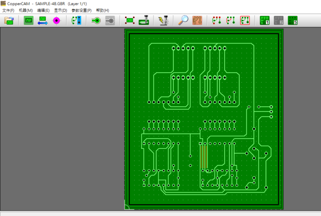
CopperCAM是個非常強的專業製作PCB雕刻軟體,可以用PROTEL設計的電路Gerber檔案轉換成雕刻機認識的G代碼。
可以產生隔離,銑削,鑽孔,銑邊等功能,可以做雙面板,操作簡單。
【PCB雕刻軟體】 CopperCAM 英文正式版 官方網址:
https://www.galaad.net/coppercam-eng.html
CopperCAM是用於管理隔離雕刻,鑽孔和切割印刷電路板原型的應用。
它不整合CNC銑床的直接驅動,而只是輸出可以由外部驅動程式軟體加載和使用的檔案或要傳送到機器的資料。
【PCB雕刻軟體】 CopperCAM 正式版主要功能如下:
– 用於Windows 95/98 / ME / NT-4/2000/2003-S / XP / Vista / 7/8/10的Native 32位程式
– 匯入Gerber&Excellon檔案,具有自動或手動對齊
– 讀取具有巨集,多邊形表面和負極性曲線的格柏RS274-X格式
– 管理4個電路層,加上鑽頭,加上切口輪廓,加上中心孔
– 通過層次等電位路徑的實時顯示
– 自動計算隔離輪廓,簡單或多重
– 圍繞墊片進行延伸隔離,用艙口自動清除
– 手動修改隔離輪廓(使用自動卡扣刪除或加入)
– 在很緊密的墊子之間執行隔離
– 選取要在路徑中心燒錄的軌道(文字,徽標或參考文獻)
– 採用鑽孔迴圈可能的鑽頭,減少刀具更換次數
– 自動計算板輪廓切割路徑,手動加入支撐橋
– 版本和校正墊片和軌道的隔膜,逐個或分組
– 根據可用的刀具管理工具庫和鑽井策略
– G代碼輸出,或HPGL,DXF,Isel-NCP,Roland RDGL等
– 完全可定制的後處理器輸出
– 自動連結加工驅動程式,或輸出到
虛擬印表機驅動程式或COM / LPT連接埠
CopperCAM工藝流程簡單:
– 開啟包括一個電路層的Gerber檔案
– 開啟下一層(最多4個),如果有的話
– 檢驗或繪製卡片切割輪廓
– 開啟Excellon檔案,如有的話
– 對齊層(自動或手動)
– 繪製作為中心線文字的曲目
– 計算隔離輪廓
– 用於去除所有銅的孵化區
– 檢查鑽具和最終的鑽孔週期
– 將輸出資料傳送到驅動程式軟體或機器
限制:Gerber和Excellon格式有許多變化,特別是對於單位和縮放系統。
因此CopperCAM不能保證所有檔案的匯入和圖層的正確自動對齊(但是您可以很容易地進行手動對齊)。
由數百或數千條細軌道的艙口製成的地平面可能非常長的隔離,計算是按軌道進行的。
如果CAD軟體可以執行,最好輸出由Gerber RS274-X格式定義的G36 / G37多邊形面。
CopperCAM is an application for managing isolation engraving, drilling and cutting printed-circuit board prototypes. It does not integrate the direct drive of a CNC milling machine, but simply outputs files that can be loaded and used by external driver software, or data to be sent to the machine. Its major functions are as follows:
– Native 32 bits program for Windows 95 / 98 / ME / NT-4 / 2000 / 2003-S / XP / Vista / 7 / 8 / 10
– Import of Gerber & Excellon files, with automatic or manual alignment
– Reading Gerber RS274-X format with macros, polygon surfaces and negative polarity traces
– Management of 4 circuit layers, plus drills, plus cut-out contours, plus centering holes
– Real-time display of equipotential paths through layers
– Automatic calculation of isolation contours, simple or multiple
– Extended isolation around pads, automatic clearance with hatches
– Manual modification of isolation contours (deletion or addition with auto-snap)
– Enforcement of isolation between very close pads
– Selection of tracks to be engraved at path centre (texts, logos or references)
– Possible drills with boring cycles, reducing the number of tool changes
– Automatic calculation of board contour cut-path, with manual addition of support bridges
– Edition and correction of diaphragms for pads and tracks, one by one or grouped
– Management of a tool library and drilling strategies depending on available cutters
– G-code output, or HPGL, DXF, Isel-NCP, Roland RDGL, etc.
– Fully customisable post-processor output
– Automatic chaining to a machining driver, or output to a
virtual printer driver or a COM / LPT port
CopperCAM process sequence is simple:
– Opening Gerber file containing one circuit layer
– Opening next layers (maximum 4), if any
– Detecting or plotting card cut-out contour
– Opening Excellon file for drillings, if any
– Aligning layers (automatic or manual)
– Plotting tracks that are centerline texts
– Calculating isolation contours
– Hatching zones for removing all the copper
– Checking drill tools and eventual boring cycles
– Sending output data to the driver software or to the machine
Limitations: there are many variations in Gerber and Excellon formats, and especially for units and scaling systems. Therefore CopperCAM cannot guarantee the import of all files and the correct automatic alignment of layers (but you can operate a manual alignment very easily). Ground-planes that are made of hatches of hundreds or thousands of thin tracks may be very long to isolate, the calculation being made track by track. If the CAD software can do it, it is better to output G36/G37 polygon surfaces that are defined by Gerber RS274-X format.